ASME Section VIII, Division 2 Pressure Vessel - Transportation Analysis
Analysis
Objective
The design of ASME Section VIII pressure vessels is generally guided by the code and FEA is not always necessary. However, with non-standard geometry, multiple construction materials and additional weight added after fabrication, analysis is frequently used to solve problems not addressed in the ASME code.
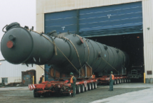
The pressure vessel in this analysis was a large shell-and-tube heat exchanger analyzed under transportation conditions. The heat exchanger was idealized with a combination of plate and beam elements as shown in Figure 1. One end of the vessel was supported with a schnabel and the other end was supported with a saddle (see Figures 2 and 3).
Once the static stress analysis was performed, the results were interrogated to ensure that the stresses did not exceed the ASME allowables (PL, PM for membrane stress and PL+PB+Q for surface stress).
This analysis was used to demonstrate that the vessel, with the additional weight of insulation, would meet the ASME Section VIII requirements during transportation with no design modifications.
PDF Download


 and Rigid Body Elements (RBEs).")
