LS-DYNA: Observations on Composite Modeling
This is the 2nd in a series of informal articles about one engineer’s usage of LS-DYNA to solve a variety of non-crash simulation problems. The first was on LS-DYNA: Observations on Implicit Analysis, the third was LS-DYNA: Observations on Explicit Meshing, and the fourth was
My academic background is in micro-mechanics and I have a good understanding of how many angels can dance on the head of a pin. A lot of my academic work was on fracture mechanics from a theoretical aspect and whenever I got into the laboratory, it was often a crazy chase in trying to correlate real-world fracture behavior to numerical models. I find the same behavior in composites. Ask ten composite experts and one can get 20 opinions. We have a myriad of theories that I don’t even want to start mentioning. My favorite reference to the uncertainties of composite analysis is that of the World Wide Failure Exercise (WWFE) where brave scientists were given raw composite data and had to make failure predictions without having access to the experimental data. Given that they couldn’t curve fit or pick their preferred layups or whatever, the reality was that theory could match experiment within 20%. This really isn’t as bad as it sounds since experimental data has a typical range of 10%.
Why Is This Important?
In the modeling of structures, the question of “how accurate is this analysis?” is always in the back of our minds. This is especially true for our clients. In composite modeling, the theorists would have us chasing our tails from one theory to the next in search of the 5% match-up between model and data. Reality is much simpler given the precision of experimental data (10%) and the accuracy of failure theories (<20%). So let’s not get too wrapped in making our failure model more complex than it needs to be. At the end of the day, when the fiber snaps it is pretty much game over and then we are quibbling about second order strengths.
Work With Something You Understand
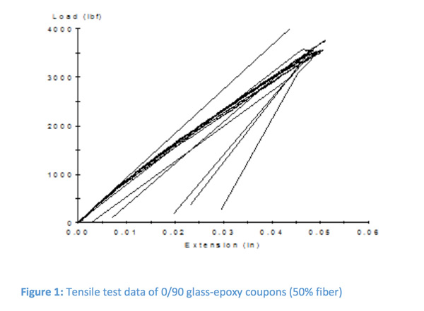
Let’s get back to fundamentals. Figure 1 shows some test data for some 0/90 glass-epoxy coupons. This is classical behavior for high-strength fiber-reinforced composites. In our practice (outside of the automotive world), when one talks about composites, it has to do with composites having fiber volume fractions greater than 40% in a resin matrix having a failure strain typically under 5%. In the fiber direction, the strength is well described by rule-of-mixtures and in the transverse direction it is pretty hopeless. Let me explain. When on pulls on a unidirectional (UD) sample transverse to the fiber, one is pulling on the matrix that has to flow around rigid cylinders. Around each cylinder a stress concentration of 3x exists. Thus, if your pure resin properties are around 5% strain to failure, you’re lucky to get 2%. Thus we have this huge ratio of strengths in UD samples to the order of 10 to 1 or as high as 20 to 1.
 In essence, all composites experience little bits of matrix cracking during loading but as long as the fibers hold, it is not a big deal. Think of it as high-cycle fatigue in metals where we are quite comfortable with dislocations moving and piling up until cracks forms until after a few millions of cycles we have micro-voids coalescing into cracks, composites pretty much do the same thing with micro-cracking of the matrix.
Practical Modeling of Composites in LS-DYNA
Although we could use UD data for our individual lamina going into our laminate, it can lead to the model being more complex than perhaps necessary. If one wanted to model a laminate using a 0/90 tape and your schedule was to lay six layers of this tape. If you modeled it classically as a UD, you would have twelve layers and twelve integration points. Upon axial loading in the 0-degree direction, all the 90 degree layers would experience matrix cracking such that the load is transferred onto the 0-degree fibers. Basically, the 90-degree layers do nothing. Keep in mind that LS-DYNA is also having to carry along the solution for twelve integration points and if you are running implicit (ELFORM=16), four in-plane integration points. All of a sudden, you’re looking around for more CPU-cores. Our approach is to keep it simple and use smeared properties for the 0/90 tape and thus reduce layers and integration points by half.
For composites, we have focused on *MAT_54 (*MAT_ENHANCED_COMPOSITE_DAMAGE). It has plenty of knobs to twist if you want to tune it for gentle damage control while at the same time, if you just want to model progressive damage (lamina-by-lamina failure) it is really simple. There are some tricks and I have provided a couple of references to shed some light on using this material model. The core concept is that strength is by-stress values and lamina failure is by-strain values. If you don’t provide strain failure values, your multi-lamina laminate will never erode but continue to hang around. With strain values, once all the laminae have failed, the element erodes. Once you play around with it and do some reading, it is a very elegant and practical formulation.
What We Recommend
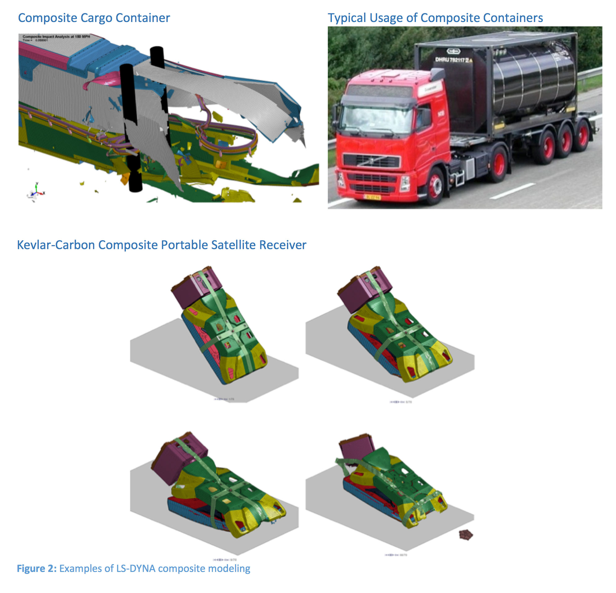
Figure 2 shows two projects that we have done using *MAT_54 coupled with *PART_COMPOSITE. The container model was quite challenging with multiple laminate and sandwich schedules and static (implicit) and dynamic (explicit) load cases. The electronics enclosure was much simpler with just Kevlar-carbon and glass laminates. The material model was developed from manufacture’s data with 0/90 and 45/45 tapes smeared into one lamina representations. For failure strains we set all the failure strains to the same value (DFAILT = DFAILM = (-)DFAILC). Although super-simple we feel it keeps us within the 20% accuracy bracket of composite reality. For the sandwich materials, LSTC support had a really useful suggestion to break up the foam core into multiple layers; thereby providing multiple integration points through the core without the hassle of defining a custom integration rule. For example, our 20 mm thick sandwich core was divided into four 5 mm thick layers. A little note on implicit is that we have found that convergence is much better with dynamics turned on since it tends to stabilize the solution as lamina fail within the laminate.
Interpreting Composite Results
All we can say it is tricky and very tribal; meaning that it seems to provide a steady stream of revenue for composite consultants. If one ignores a lot of this chatter and sticks to basics it is not that hard. The utility of modeling with progressive damage is that it captures the true stress-deflection response of the structure. As load is applied and fibers break, the load is shifted onto the remaining lamina and the stiffness of the composite is updated. Standard linear analysis completely ignores changes in laminate/sandwich stiffness due to ply failure. It is one of the great advantages of a nonlinear approach. Although one can argue that given force based loading and that most composite structures fail under bending, it is a moot point since once the outer fibers fail, the remaining plies quickly follow. I would counter and say that given complex structures with integrated metallic components (frames, closures, panels, etc.) and varied composite schedules, it is hard to predict where the load path might end up and if the load is displacement based, progressive damage is the better method.
Of course “careful interpretation” means different things to different analysts but here is our short list:
o Be aware that all holes have a stress concentration of 3x
o Classical plate theory assumes no out-of-plane deformation and constant strain through thickness (e.g., see *CONTROL_SHELL, LAMSHT=1)
o Where ever the composite ends in a free edge or is joined to another composite or metallic component, be nervous and make sure you understand its behavior
o Contour your global failure indices and ensure they are logical
Lastly, if you material model is logical and matches the experimental stress-strain behavior and you understand the loading on your structure (another source of uncertainty), most likely your model will be within 20%. And just remember that all models are wrong.
Some Reference Materials
From LSTC, we have your core reference:
http://ftp.lstc.com/anonymous/outgoing/jday/composites/mat_comp.pdf
And Google’able items:
“Composite Damage Material Modeling for Crash Simulation: MAT54 & the Efforts of the CMH-17 Numerical Round Robin” by Wade et al.
AWG LS-DYNA Modeling Guidelines
Crashworthiness Analysis with Enhanced Composite Material Models in LS-DYNA – Merits and Limits” by Schweizerhof et al.