Large Manufacturing Facility HVAC Analysis
Analysis
Objective
The objective of this analysis was to verify the HVAC design of a large manufacturing facility. The facility provided a complex thermal problem with many localized temperature extremes. Additionally, the facility experienced extreme winter and summer conditions that would test the limits of the HVAC design.
Before tackling the analysis of the complete facility, two sections of the building were analyzed to explore the most harsh summer and winter operating conditions. These sections were chosen carefully to ensure that they represent the most challenging scenarios for cooling and heating.
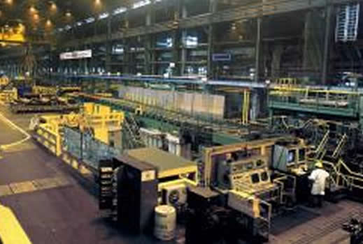
Once the modeling techniques had been proven on the subsections of the facility, it was time to build a comprehensive model. This model included circulation fans, HVAC ducting, gas heaters, lighting, air drafts from unsealed doors, heat loads from manufacturing equipment, and other temperature and flow inputs (see Figure 1).
The results of this analysis provided the client temperature, air velocity, and flow path throughout the facility (see Figures 2-4). This analysis demonstrated that the HVAC design would be adequate in even the most severe conditions and modification to the design was unnecessary.
Keywords: HVAC Analysis, CFD Consulting, Autodesk Simulation, Autodesk CFD Simulation, Incompressible Flow, Computational Fluid Dynamics, Building Flow, HVAC, Air Temperature, Air Flow, CFD Consultants.
PDF Download


