Thermal Stress Analysis of Large-Scale Evaporator-Condenser Set
Analysis
Objective
Under the ASME Code, Section VIII, Division I, Rules for Design and Fabrication of Pressure Vessels, a broad array of design formulas can be utilized in the design of robust and safe process equipment. But experience has shown that these rules are often over-conservative and add manufacturing costs that are often unnecessary. This case study shows how our pressure vessel consultants were able to classify this vessel fit-for-service under ASME's Division 2 design-by-analysis rules.
ASME Section VIII, Division 1 rules can be overly conservative or may not be directly applicable to unique combinations of thermal, pressure, and possibly external primary or secondary loadings. This combined with non-standard geometries and/or expensive construction materials, present design challenges that become prime candidates for finite element analysis (FEA). The use of FEA in these special cases provides an opportunity to meet ASME Section VIII, Division 2 design-by-analysis requirements while optimizing the structure for stress, ease of manufacturing, and material cost control.
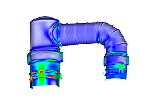
The equipment shown in the adjacent figures consists of an integrated evaporator and surface condenser set. Vaporized product is transferred between the two vessels via a large diameter communicating section. Within each vessel, thick tube sheets and reinforced shell sections constrain the thousands of heat transfer tubes. Process requirements require that each compartment (shellside or tubeside) have its own set of design and operating pressure/temperature parameters. Each vessel is individually supported and fixed to structural steel, with the communicating chamber connected and supported at each end by the respective vessel to which it is attached. The load case consisted of applying thermal loads to the heat transfer tubes, and thermal + pressure loads to shell compartments and the communicating chamber. The combined thermal/structural analysis produced a complete stress and deformation view of the vessel set under worst-case conditions (as defined by the client). A fatigue assessment was then made to ensure that the vessel would meet all service requirements. Results from this analysis were then used to document the strength and safety of the design and satisfy applicable ASME requirements.
Modeling Notes: The vessel model was constructed using plate elements for all shell surfaces and beam elements for the heat exchanger tubes. The beam elements were connected to the tube sheets via RBE3 interpolation elements. Bolted connections between the flanges were similarly modeled using beam and RBE3 elements. The model was extremely efficient and solution times were in minutes (the model had over 750,000 DOF). All analysis work was done using Femap and Nastran.
PDF Download


