FEA Quiz
Welcome to our little FEA quiz. We have tried to make the questions relevant toward the evaluation of the engineer who has a background in finite element analysis. Saying that, knowing the answers to this quiz doesn't imply that one is capable of building accurate simulations, merely that one is heading in the right direction and has a good sense of humor.
If you had one steel and one aluminum cylinder of equal cross-sectional areas (1 sq-in) and both cylinders are loaded with a force of 100 lbf, which cylinder will have the higher stress? By how much would you expect the stress values to differ?
The stress will be the same regardless of material used - since stress is F/A.
You have just meshed a solid CAD piece of geometry using 10-node Tetrahedral elements and have applied a fully fixed constraint (all translations (TX, TY, and TZ) and all rotations (RX, RY, and RZ) are fixed) to one node of the structure. What action is enforced by the RX, RY, and RZ constraints? Would you expect the structure to be sufficiently constrained for a static stress analysis? If not, how many nodes would have to be constrained to "fix" the model for a stress analysis?
No action. 10-node Tetrahedral elements do not have RX, RY, and RZ degree-of-freedoms. The structure would not be sufficiently constrained. A minimum of three nodes.
What material property data is required for linear, elastic static analysis?
For a linear, static analysis you only need E, n or G, n. If you were also incorporating body loads, e.g., gravity, then you would need the density of the material.
You have applied a uniform internal pressure to a cylinder and would like to check your work. You then use your FEA pre-processor to perform a sum-of-forces calculation. What value would you expect to be returned by the sum-of-forces calculation?
0.0
You have just finished a rather complicated linear, elastic, static stress analysis using a low cost 1018 steel with a yield stress of 36,000 psi. The peak stress in the structure is 52,000 psi. The engineering group has decided to use a more expensive AISI 4340 steel with a yield stress of around 80,000 psi. Upon implementing this new material into your FEA database, how would you expect the analysis results to change?
No change since you are performing a linear stress analysis.
What is the mathematical description of symmetry as used in the FEA world? How many planes-of-symmetry could be used for a uniformly loaded plate with a hole at its center?
Really basic but tricky to really understand and implement. A plane-of-symmetry will have translation normal to its plane fixed and in-plane rotations fixed. For example, if our plane-of-symmetry rests within the XY plane with the Z-axis normal to this plane, a plane-of symmetry could be enforced by fixing the Z degree-of-freedoms and the RX and RY rotational degree-of-freedoms. If you got the above answer, then this second part is a slam-dunk: two planes for 2-D and three planes for 3-D.
How would you apply symmetry in a thermal analysis? In other words, what boundary conditions would you apply?
Thermal symmetry is really an adiabatic condition, with no heat flowing across the symmetry surfaces. The answer is that you would do nothing; leave the surface as a free surface. Free surfaces are by definition adiabatic.
You have a disk structure with a hole at its center (let us say that it is 12 inches in diameter and 0.1 inch thick). The center of the plate (the hole perimeter) is fixed and a displacement load is applied around the outer edges of the plate. The structure is similar to a "clutch plate" used in an auto transmission. The displacement load is normal to the disk creating large bending stresses within the disk. If your goal is lower the stresses within the disk, would you make the disk thicker or thinner? Secondly, would it make sense to switch to a lower modulus material (say switching from steel to aluminum)?
Since the structure is under bending due a fixed displacement load, the stresses in the plate can be lowered by making it thinner. The trick is to remember how flexible sheet metal is compared to a bar of steel. The equation that governs this behavior can be roughly stated that the applied force is proportional to the displacement times the elastic modulus times the cross-sectional moment of inertia (I). Consequently, if we make the plate thinner, the moment of inertia will decrease yielding less force and thus lower bending stresses. The same argument holds for lowering the elastic modulus, that is, we would see the stress decrease by a factor of 3 by switching from steel to aluminum.
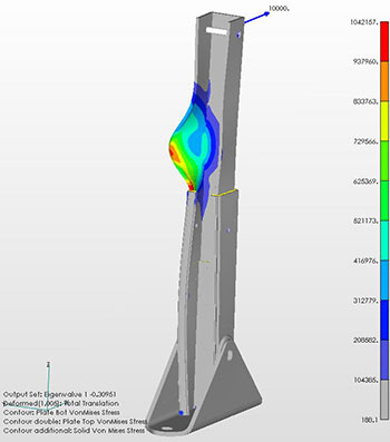
A buckling analysis has been requested of this simple C-channel structure. The load is in the positive X-direction and is applied through a beam element (simulating a large bolt) which is then connected to the plate elements via rigid links. The buckling analysis option is selected and the analysis proceeds. When the analysis completes, the first eigenvalue buckling mode is negative! For this particular model, the negative eigenvalue is -0.35. This would indicate a buckling load of -0.35*10,000 lbf = -3,500 lbf. Is this a valid result and what does it mean?
For clarity, here's a picture of the structure with the applied load:

Yes, this is a valid result. The negative value indicates that the buckling mode is reversed from the direction of the applied load. Looking at the structure one can see how one of the sides of the C-channel has buckled and it makes structural sense.
You have just run this very complicated linear analysis with several different type of materials and linear contact behavior between two of the bodies within your structure. Upon post-processing the results you see that the von Mises stress scalar ranges from a very high value (say 135,000 psi) to a low value that is negative (say -57,000 psi). What would the analysis results be telling you?
Von Mises stress scalar is always positive. Yes - a trick question.
In modeling a very long I-Beam (6" flanges with a 10" deep web) using quad plate elements (since you are aware of the deficiencies of 3-node triangular plate elements), you would like to use the absolute minimum number of plate elements through the web since this I-Beam is part of a much larger model. How many elements would you use through the cross-section of the web for an accurate deflection analysis (say within 5% of an analytical solution)? Would you bump up the number of elements if you desired higher accuracy stress numbers or not?
The standard is four elements. Although some people feel that three is sufficient. If high-accuracy stress numbers are desired, then five to six elements through the web would be the target. The reason is that deflection data is first order information (F=K*U) while stress information is second order (stress=E*strain) and must be calculated from displacements using the element’s shape function.
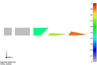
When your FEA buddy Sara boasts about her low Jacobians; is your response "Way to go Sara" or "What was that again... Jacobian what?"
The Jacobian is just a linear transformation matrix that is used to convert the element’s global coordinates into a -1 to +1 coordinate frame. It is a linear operator like Y=A*X and the Jacobian is the "A". Since it is converting your element’s global coordinates into a unit coordinate system, a perfect 1x1 element would have a perfect Jacobian. Typically, most codes will equate a perfect Jacobian with 0.0. Thus our "A" actually is (1-Jacobian) and for high-quality elements Y=X and we have a very clean transformation. If the element becomes distorted, the Jacobian will climb upwards. For a highly distorted element with a Jacobian near 1.0, the transformation fails. With most FEA solvers, an error code will be printed out for Jacobians higher than 0.8 (for example the elements shown on the right in the graphic).
What is the minimal number of Timoshenko or Euler-Bernoulli type beam elements that is necessary to model a simply supported beam, if one only needs to extract the maximum deflection and stress at the mid-point of the symmetric structure under uniform loading?
This is a logic question that tests your understanding of beam theory and symmetry. Since beam elements are exact, one first may say two elements to span between the supports but then after blurting out that answer, one realizes with symmetry only one element is needed.
You have a tricky design problem and we'll use the cantilevered beam as our illustrative example. You are given a fixed downward displacement at the end of the beam, to lower the peak stress, do you increase or decrease the thickness of the beam?
If you think you have the right answer, then let's say that your stress is 210 MPa and you have modeled the beam using steel. What would be the stress if you switched to aluminum?
Since it is a fixed displacement your stress would go down if you make the beam more flexible, i.e., with a decreased thickness. Likewise, since for deflection problems, stress is proportional to the elastic modulus, you could cut the stress down to 70 MPa by switching to aluminum since its elastic modulus is 1/3 of steel.
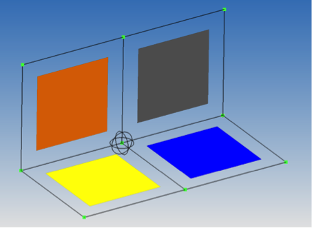
Beams elements provide the ultimate in FEA optimization but with this power comes a bit of complexity. Just to make you nervous, do you know which cross section or sections would twist if a vertical load was applied through the point drawn on the image? Now, which image shows the load applied at the beam’s shear center? Lastly, if you are feeling brave, what is the difference between a beam’s shear center and its centroid?
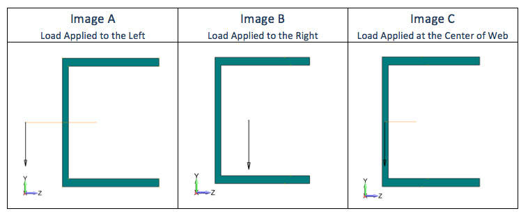
A load applied as drawn on Image B and C would cause the beam to twist around the x-axis. In Image A, the load is drawn through the beam’s shear center and the beam will not twist. This is the default for many FEA pre-processors.
Image A shows the load through the shear center while Image B shows the load through the beam’s centroid. Loads applied through the shear center of a cross-section do not induce twist while an axial load applied through the centroid will not cause the beam to bend. Additionally, if it is a moment load (in Image B it would be Mz or My), the beam will only bend and no axial strain will occur. This statement from the literatures sums it up well “…..the load acting at the centroid decouples the structural response between axial extension and bending, whereas, shear center decouples bending and twisting, mechanisms of a beam.” Courtesy of W. S. Chan et al. “Determination of Centroid and Shear Center Locations of Composite Box Beams.”
Timoshenko Beam Theory is a fundamental method to calculate stress at any point in a beam. Beam stress is given as:
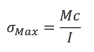
This formula is for the maximum stress in a beam under uniform bending and, of course, given a constant cross section. Now, in the case of Nastran and other linear, implicit codes, beam stresses are recovered at specific locations as determined by the analyst. For example, here’s an image from FEMAP showing the four stress recovery locations for a beam:
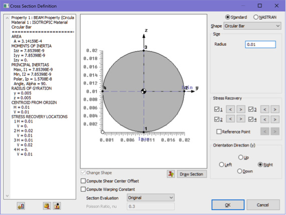
Now comes the question, you are requesting that the stress recovery points are to be located along the orthogonal axis of the beam. In this case, the moment is created by a force oriented at 45 degrees from the orthogonal axes. This means that the maximum moment is not aligned with the orthogonal axis. Let’s say for simplicity that our hand crank says that the maximum stress should be 1,000 MPa. What would be the number returned for any analysis program using the above arrangement of stress recovery points?
Multiple Choice Answers
- 1,000 MPa
- 707.1 MPa
- 1,414 MPa
- 2,000 MPa
The correct answer for the maximum stress is 1,000 MPa; however, given the location of the stress recovery points, the program will return a maximum stress of 707.1 MPa. This is the limitation of using stress recovery points. It will only report the stress that the simulation engineer requests and in this case, the maximum stress is located at 45 degrees from the axis. This seems obvious now but caused a bit of consternation when we first studied this problem due a technical support request.
An inside joke, when we look for new hires at Predictive Engineering we look for engineers that like to read. What it really means is that we look for talent that believes in continuous learning. This cartoon (borrowed from one of Dr. Patrick Safarian’s presentations) provides a comical view of what happens when one stops learning.

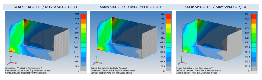
This question comes courtesy of an interaction that we had with a senior structural engineer and also provides an instructive lesson to engineers new to stress analysis. Let’s say you are building small aluminum boats that have many sharp corners where stringers are attached to the hull or at bulkheads. Based on the geometry of the boat, it is idealized using plate elements with many sharp (90 degree) intersections at welded seams. Given the importance of your analysis work on the safety of these boats, you decide to perform a mesh convergence study using mesh sizes of 2.0, 0.5 and 0.1. The model is just an open box with a length of 80” and a wall thickness of 4”. The results are shown below:
You are then asked to defend your results by answering the following questions:
1.) Has the mesh converged? Yes or No? Also, please explain your decision to choose either Yes or No.
2.) Where would be the logical location to interrogate your model given that the plate elements are 4” thick?
(a) Where the two plates join
(b) At 2” away from the corner
(c) At 2” away from the corner plus an allowance for the fillet weld thickness
(d) At 4” away from the corner
(e) None of the above
Bonus Question
3.) Understanding the mathematical formulation of isoparametric elements and how stresses are calculated within these elements, how should the nodal stress be displayed along the sharp junction shown in the figure below?
(a) Display in-plane average nodal values but no averaging across the junction
(b) Display max nodal values from connected elements
(c) Display average nodal values from connected elements
(d) Display averaged centroid stress values across the junction
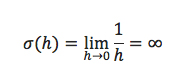
1.) No. A sharp corner has asymptotic stress behavior approaching infinity or as one of our engineers reminded me as he read this note: “….the stress, σ, at the intersection of 90 degree plates approaches infinity (un-bounded) as the mesh size, h, approaches zero;
Thus, the stress will just keep increasing as the mesh is refined. In the real world, the spherical chicken doesn't exist and neither does the perfectly sharp corner. Given that a 4” steel plate would be welded onto another plate to form this corner, the weld bead would eliminate the sharp corner and the stress would be bounded. As one can guess, this whole mesh convergent study would be a grand waste of time since one would be chasing your own tail.
2.) (c). Given the nature of plate element modeling, the corner region will be excessively stiff and act as a stress concentrator since one has two 4” thick plates overlapping. Hence, the stress at the corner is not accurate. One of the most respected standards in the industry, the ASME BPVC Section VIII, Division 2, specifies that stresses should only be interrogated away from the plate junction as listed in (c).
Bonus Question
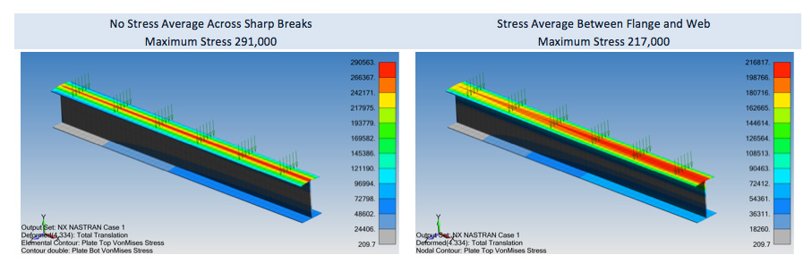
3.) (a). I explain the rational not to average (B.T.W., not to average is a generally accepted practice or G.A.P.) by visualizing an tall I-BEAM that only has two plates elements through its web. If one is to average the stresses at the joint between the web and flange, one would notice that the stresses would drop along this seam. This makes no sense and one can see that it can also lead to under-predicting the accurate stress state in the structure.
Thank you for reading this far. It is my hope that by writing up this question that I can instill a bit of curiosity and respect for learning new things and likewise, that building good simulation models is 99% hard work and 1% inspiration (thank you Thomas Edison).