Thermal Analysis of Innovative LED Light Assembly
Analysis
Objective
Our client is an innovative leader in the field of LED light bars that can generate intense UV light for a variety of industrial applications. These LED light bars present a unique thermal challenges due to their high power and compact environments.
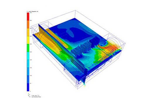
Predictive Engineering was contacted to execute a CFD simulation on an extremely tight timeline. The objective was to verify that their new compact design could still provide sufficient cooling to keep chip lead temperatures at acceptable levels for long duty cycles. The thermal challenge was that each LED module had very high power loads and the back-plane of each chip was coupled to a large heat sink. As part of our CFD optimization study, we tried out various thermal greases and heat sink combinations. Toward the end of the project, it was required to directly baffle the fan stream onto the hotter heat sinks. Interpretation of the CFD results showed that some chip leads had acceptable temperatures while others, due to their proximity with other power-dissipating chips remained quite hot. Through thermal management, additional heat sinks were added to distribute the thermal energy and arrive at an acceptable solution. This project represented quite a bit of teamwork between our CFD consultants and our clients designers to arrive at the final configuration.
Modeling Assumptions and Details: The CFD model was constructed based on 3-D geometry provided by our client. This geometry was slightly simplified for improved numerical performance.
All flow was driven by a 40x40x28 Sunon fan that could deliver 24 CFM at 0.0 inch H20 backpressure. The fan curve was directly integrated into the CFD model. The flow through the light box was restricted by an exit baffle with 25% of its cross-sectional area blocked (75% open). This flow restriction increased the internal pressure within the box and preferentially drove a portion of the air stream through the exit passages drilled into the box alongside the high power LED arrays.
Aluminum was used for all heat sinks. The heat generating chips were modeled as ceramic. A thermal interface compound was used between the high power LED arrays and its massive aluminum heat sink. The trade name for this thermal compound is Silverstrate.
The thermal load case consisted of the high-power LED arrays, FETs and the circuit board. This project is also similar to the work we have done at www.predictiveengineering.com/consulting/cfd/computational-fluid-dynamics-cfd-analysis-automated-test-equipment
Summary: Results were delivered on time and validated the design intent with only a few design iterations. The product has gone into production and our results were validated. As CFD consultants, seeing our results validated is our number one goal - bar none.


