Cold-Spinning of Engines via the Perfect Drivetrain: Static and Eigenvalue Analysis
Analysis
Objective
When new car or truck engines are manufactured, a cold spin-up test is often performed. During this test, the engine is spun while vibration transducers, accelerometers and pressure gauges measure the engine’s performance.
Ideally, the drive motor that is doing the spinning only transmits pure, clean torque energy to the test motor. Development of a high-stiffness yet well damped drivetrain between the drive motor and the test engine has been and still is a development challenge for many companies.
Drivetrain analysis is mainly about getting the right dynamic response out of a collection of mechanical components. The proposed drivetrain started out with a Lovejoy torsional coupler and then proceeded through a steel driveline shaft followed by a very tricky steel bellows. At both ends of this system, we had a varous assortment of steel couplers. Although each component had its own linear dynamic response, the assembleage of these components presented an interesting numerical challenge.
The finite element model was built using brick elements (hexes), tetrahedrals (tets), beam elements, spring elements and rigid links. Although all of these elements are linear in nature, their combined response was not easily predictable. Once assemblied the model was run as an eigenvalue analysis and predictions were made.
Software tools: Femap and NX Nastran
PDF Download
Cold Spinning of Diesel Motors to Determine Start-Up Vibration Problems
Dynamic Engine Drivetrain Modeling
This engineering project evaluates the dynamic performance of a cold-engine test stand. The below graphic shows the test engine on the right with the test stand on the left.

Dynamic Engine Drivetrain Modeling
From CAD to FEA. It may look direct but there is a lot of sophistication in the idealization of this structure into a predictive numerical model.

Dynamic Engine Drivetrain Modeling
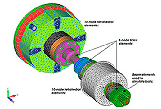
Geometry set was idealized into a finite element analysis (FEA) model. The model was meshed using 10- node tetrahedral and 8-node brick solid elements. The bolted connections (not shown) were modeled using a combination of beam elements for the bolts and rigid links as the connection "glue" between the bolts and the components.
 model. The model was meshed using 10- node tetrahedral and 8-node brick solid elements.")
Dynamic Engine Drivetrain Modeling
Various components (Rubber Couplings, Steel Shaft) idealized into the FEA Vibration Model. Digital Prototyping of Vibratory Systems.

Dynamic Engine Drivetrain Modeling
Vibration Eigenmodes in the simulated drivetrain
