Lift Truck Analysis and Validation

A detailed finite element analysis (FEA) was done on a new lift-truck design. The analysis work was validated against the as-built lift-truck and shown to accurate predict tower deflections under load.
Analyzed a completely new lift truck design leveraging existing commercially viable designs from other manufacturers. The mechanical analysis included the whole lift truck structure from boom to hydraulic cylinders to engine compartment frame to the axles. The FEA model (Femap) used plates, beams, rigid links, gap elements, solid elements, and springs. The boom truck was exercised through its design envelope on the computer and optimized for strength and weight.
Modeling Notes: The final engineering design was built and lift tests were performed. All design criteria were met and the lift truck is now in production.
Full FEA case study (PDF)
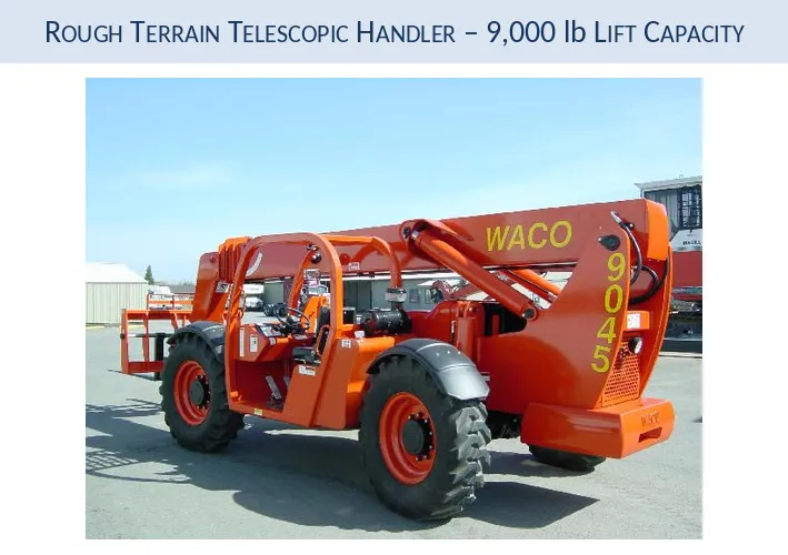
Rough Terrain Telescopic Handler
WACO Lift Trucks & Attachments rough terrain telescopic handler. The truck is rated at 9,000 lb lift capacity.
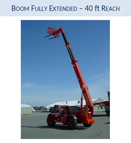
Boom Fully Extended
With the boom fully extended, the truck has a reach of 40 ft.
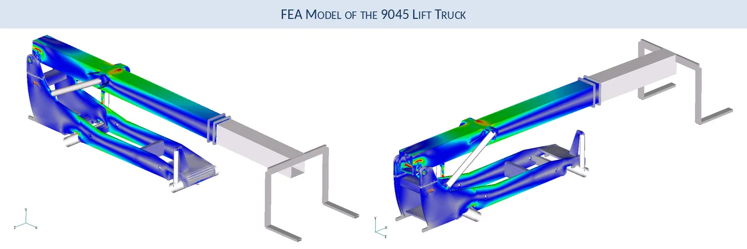
FEA Model of the Lift Truck
FEA model of the WACO 9045 lift truck.
Element Types in the Truck FEA Model
The truck FEA model required the use of a wide range of element types. For example, the hydraulic cylinders were modeled with beam elements, the boom with plates, and the truck body with hex and plate elements. Gap and rigid link elements were used to simulate the interaction between the boom pin / boom / and truck body.
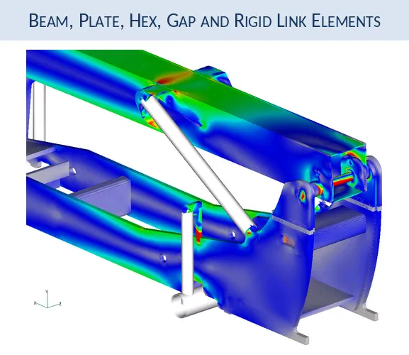
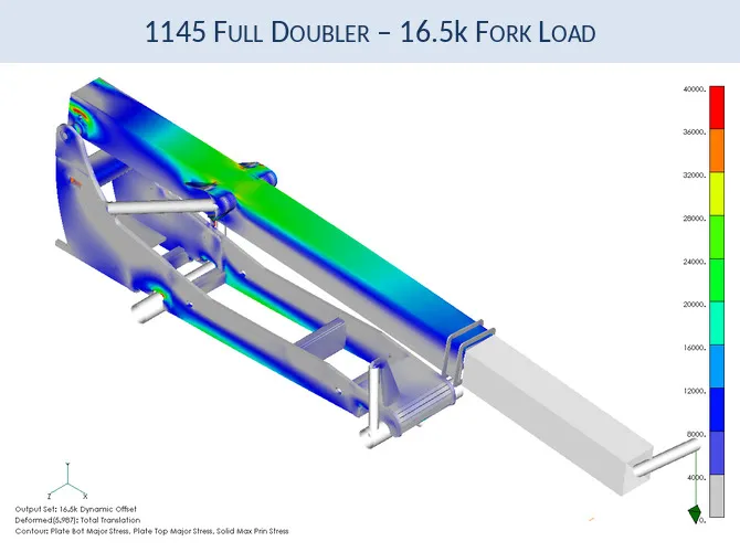
WACO 1145 Full Doubler: 16.5k Fork Load
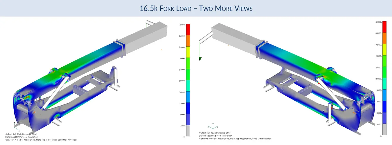
WACO truck 1145 model. The 16,500 lbf is hanging off of one fork in the front. The stress legend is capped or limited to 40,000 psi to better display the stresses on the boom and the side plates. Individual peak stresses within specific components will be discussed in subsequent slides.
Outrigger Arm Under Worst-Case Load
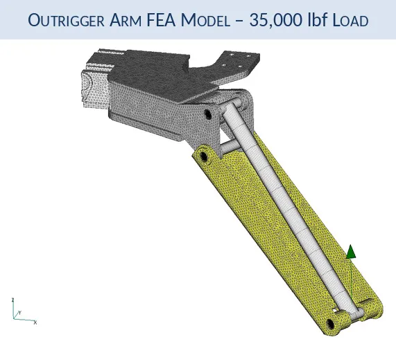
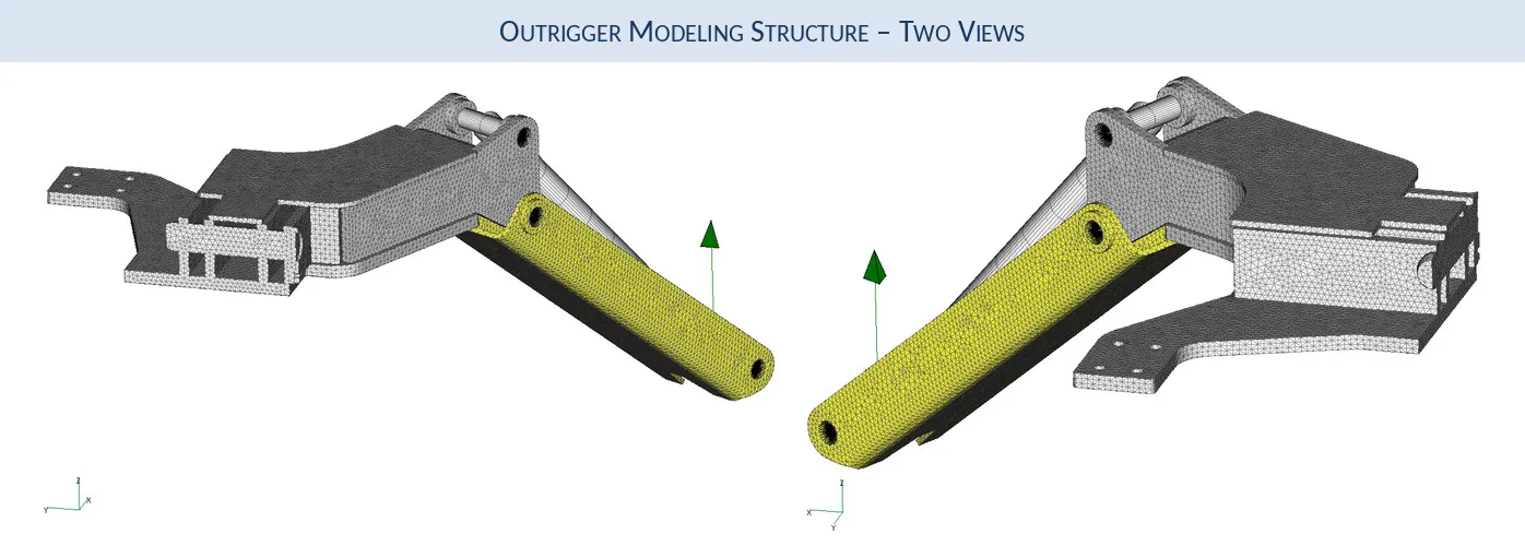
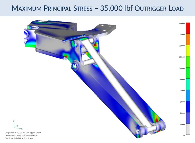
Under worst case conditions, one outrigger arm would support the total load carried by the front axle. Under full design load (11,000 lbf load X 1.5 dynamic bounce factor = 16,500 lbf) of 16.5klbf, one outrigger carries a load of 35,000 lbf. The pins and hydraulic cylinder were modeled as simple beams to facilitate load transfer between the parts.
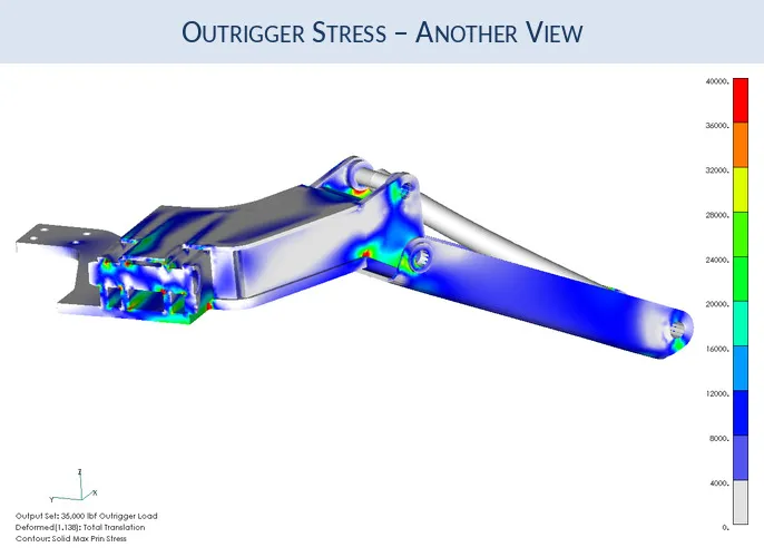
Maximum Principal Stress in the Outrigger
The maximum principal stress is contoured over the structure. This stress vector is dominantly tensile and correlates extremely well with fracture initiation under single occurrence peak loads. The legend is capped at 40,000 psi. The deflection of the part is magnified by a factor of 5x.
Predictive Engineering – The Advantage of Getting it Right the First Time