Norton Motorcycle Crankcase Analysis
Analysis
Objective
Being a long time enthusiast for all things with two wheels, it was a blast to have an opportunity to work with Norton Motorcycles on the development of their next-generation bike. Their challenge was to validate the structural behavior of their new aluminum engine block which was designed from the ground up.
Analysis Challenge:
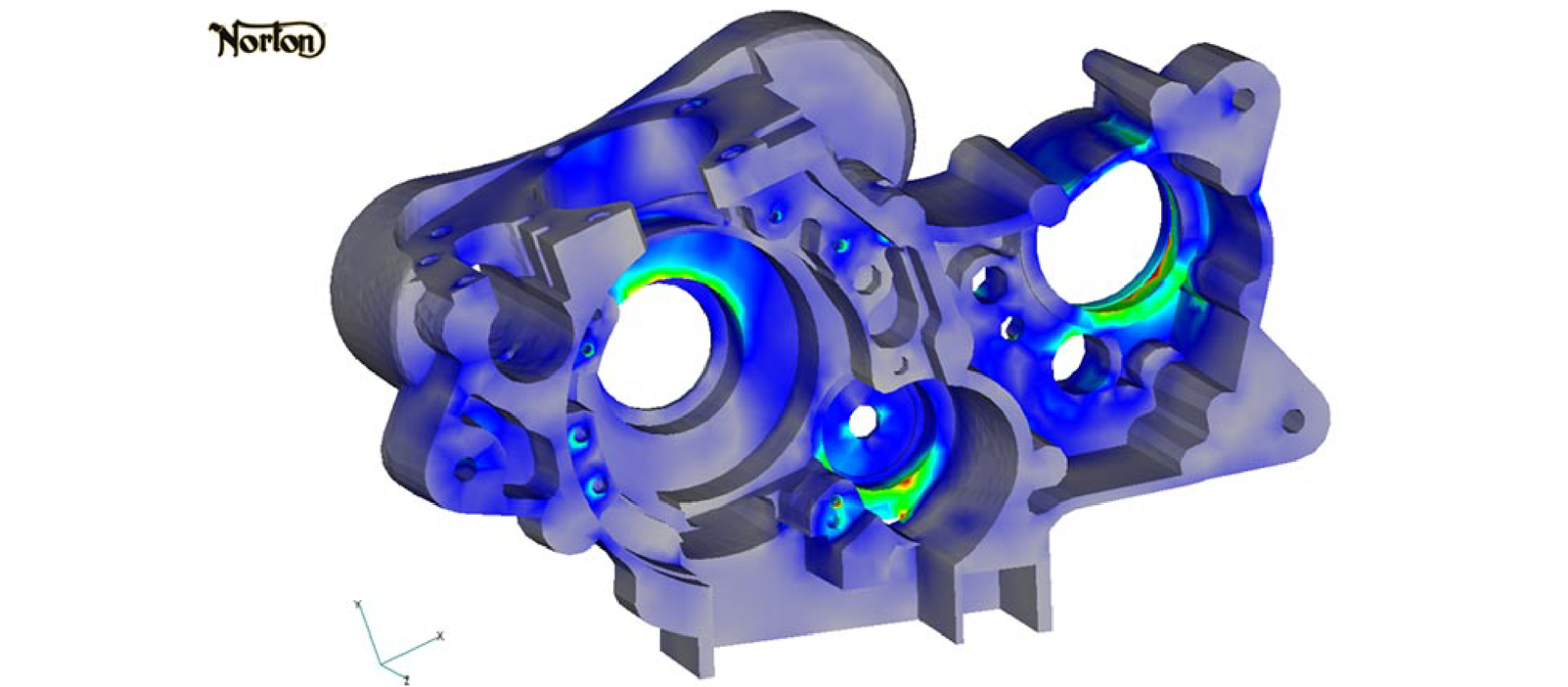
However, the real challenge was calculating the various load sets.Along with the main crankshaft power stroke, inertia forces from the main crankshaft and balance-shaft must be considered, and of course, the traction torque of the chain. As the engine is cycled from full power to full RPM, various peak forces are encountered in different regions of the motor drivetrain. I wish I could take credit for figuring this stuff out but my engineering hat is off to the team at Norton Motorcycles. They were able to supply me with detailed calculations for all major load cases along with "lessons" on how motorcycle engines really work and why the HP versus RPM curve flattens out and starts to decrease when a certain RPM level is exceeded. This collaborative project is on track and with some luck, a new breed of Nortons should be seen on the streets in the near future.
Modeling Notes:
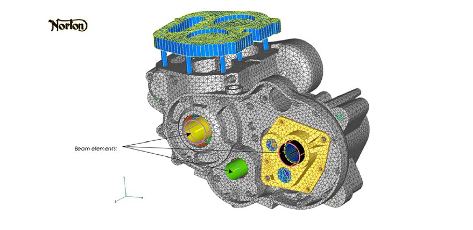
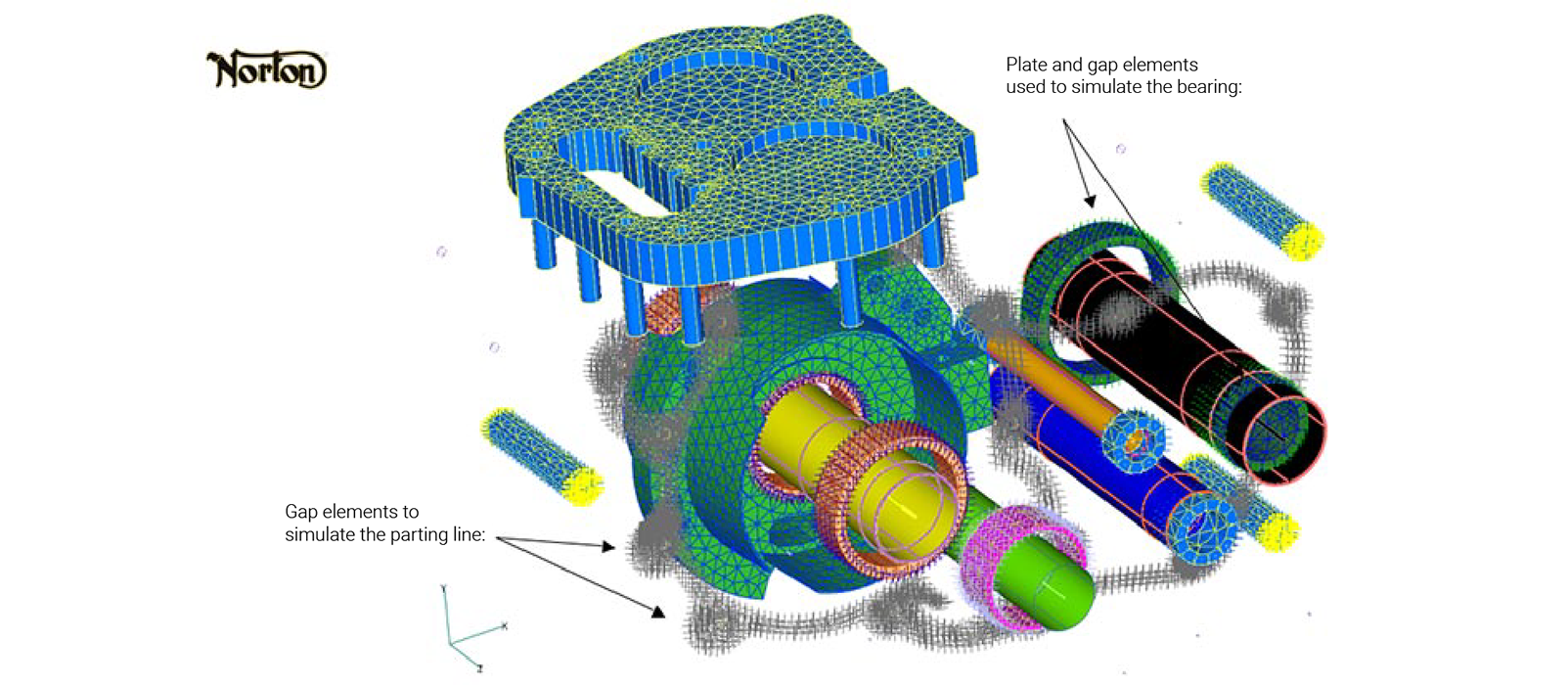
The finite element model was meshed using SolidWorks parasolid geometry provided by Norton Motorcycles. The solid portions of the model reflect the exact geometry of the prototype crankcase. The crankcase shaft, balance shaft and transmission shafts were modeled using beam elements. The bearings of these shafts were modeled using plate elements that are connected via gap elements (nonlinear elements that can bear compressive loads but not tensile loads) to the solid FEA model. This arrangement allows the shaft loads to be distributed onto the crankcase bearing seats in a uniform "bearing-like" manner. That is, only compressive forces normal to the crankcase bearing seat are applied. The bearings and shafts were considered somewhat rigid. This is a reasonable assumption given that the bearings and shafts are steel and the crankcase is aluminum. Complete contact behavior was simulated between all bearing surfaces and all corresponding crankcase surfaces.
The parting line mechanical behavior was enforced using gap elements to simulate the contact behavior between the two halves of the crankcase. The crankcase parting line bolts were also pretensioned in the analysis procedure. A nominal bolt pretension force was used. This was estimated to be reasonable given the diameter of the bolt and the resulting stresses within the aluminum crankcase under this bolt preload. This bolt preload should be refined if subsequent work is pursued. However, for this initial analysis work, it provides a reasonable engineering approximation of the bolt/crankcase behavior.
NX Nastran V3.0 was used for all analysis work with Femap V9.0.1 as the pre- and post-processor.
PDF Download
Femap model of Norton Engine Crankcase
This interior view of the crankcase model shows an outline of the beam elements used to idealize the crackshaft, balance shaft, lay shaft and transmission shaft. Althought it is difficult to show on this graphic, the loads are applied to the beam elements wich then distribute the forces onto the bearing seats of the crackcase structure through a network of plate and gap elements (not shown).
Note:gap elements are nonlinear elements that can carry compressice loads but not tensile loads. They are very useful for modeling contact interfaces that bear compressive forces but not tensile loads normal to the interface (e.g. like bearings and parting line seals).
