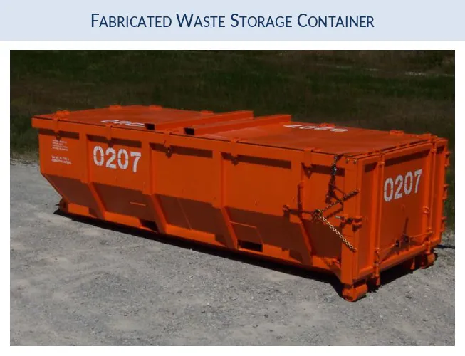
Drop Test Analysis of Large Nuclear Waste Storage Containers

The U.S. Department of Transportation specification 49 CFR 173 calls out a rigorous series of testing procedures for containers that are used to transport hazardous waste. One requirement is that the container survive a drop test from certain height The height of the drop test is determined by the weight of the container.
As the weight of the container increases, the drop height decreases. As an example, a 60,000 lbf container must survive a drop from 12" onto its most vulnerable corner. Over the years, as the sophistication of computer programs has increased and the accuracy of the real world simulations has improved, the DOT has allowed the substitution of conservative numerical results for actual drop testing. A numerical standard in the industry for drop testing is LS-DYNA from LSTC (see www.LSTC.com). This explicit/implicit FEA code is quite amazing in its ability to accurately capture extreme nonlinearities in a transient event. Although its bread and butter is the simulation of car crashes...the drop testing of large steel containers and the high speed impact analysis of cars are quite similar. Both involve dynamic events where multiple contacting surfaces must be handled quickly and large plastic strains dealt with in a realistic manner.
The successful completion of this project owes many thanks to the fine engineering tools provided by LSTC (the manufacturers of LS-DYNA) and by Siemens (the manufacturers of FEMAP and NX CAD). Not only are their software tools world class but their technical support infrastructure is second to none.
The key analysis words for this project are: LS-DYNA, Femap, Impact Analysis, Drop Testing, and DOT 49CFR173
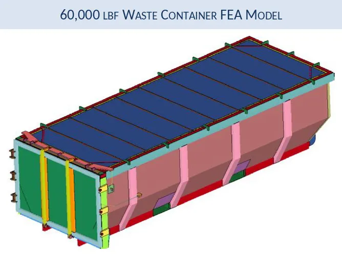
Container FEA Model
The container weighs 60,000 lbf fully loaded and per DOT 49CFR-173 specifications must be able to survive at 12” drop onto its most vulnerable corner. To ensure some margin of robustness, the container was virtually dropped from 15" providing a drop energy level of 125% of the DOT specifications.
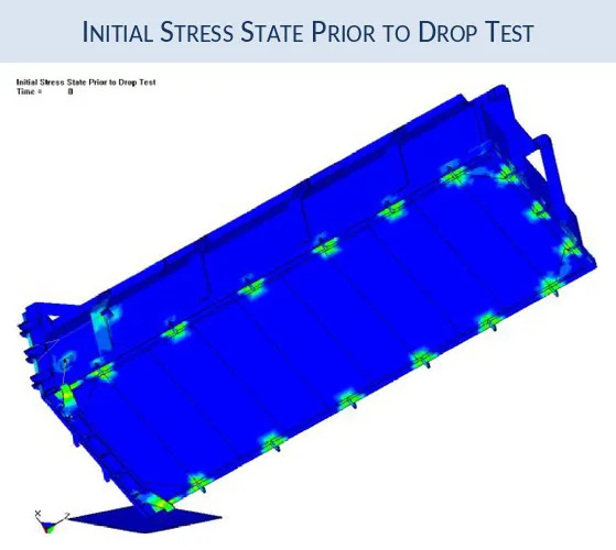
Pre-Tensioned Clamps and Initial Stress State
The FEA model was exported from FEMAP into LSTC´s LSPrePost (see www.LSTC.com) where final LS-DYNA specific modeling adjustaments were made. For example, the id and door clamps were pre-tensioned using a dynamic-relaxation analysis routine within LS-DYNA prior to the initialization of the drop test. This allows us to correct simulate the pre-tensioned state of the numerous id and door clamps. There pre-impact stress state is shown below.
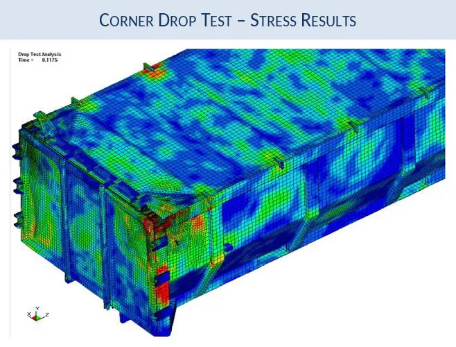
Corner Drop Results
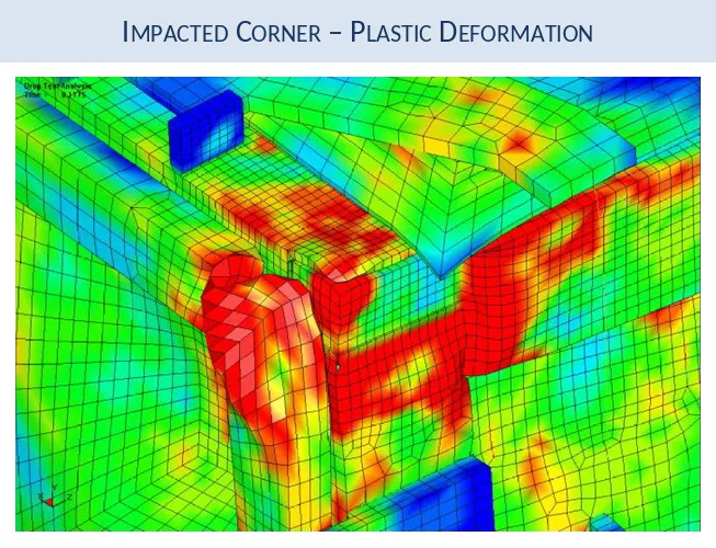
The container model was dropped onto its most vulnerable corner and allow ed to deform under its initial velocity and the effect of gravity. Extensive elastic/plastic deformation occurred at the Impacted corner. This model was quite complex with about 30+ surfaces that were required to interact via a surface-to-surface contact algorithum. Along with the pre-tensioned clamps, the model used plate, beam, cable, and solid elements.
Design Iteration
The initial container design talled due to extensive plastic deformation in the door tube and underneath the upper edge of the id corner. Lessons learned from this early simulation eventually led to the final, winning design.
From Model to Fabrication
When you are modeling...sometimes you wonder if it will ever be built?