Linear and Nonlinear Buckling Analysis and Flange Crippling
Objective
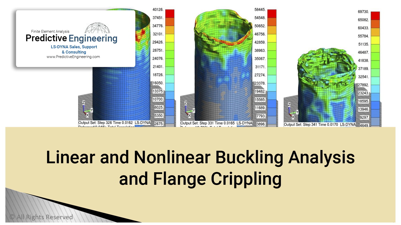
This white paper will walk you through the use of NX Nastran and LS-DYNA to do classical Eulerian Buckling, geometric nonlinear buckling and complete, full-physics nonlinear buckling (LS-DYNA). We will also show you how to validate your linear buckling analysis with a non-liner static analysis. Additional examples are presented on flange crippling and then finally the application of these techniques to the buckling analysis of a beer can and then an eight-passenger, deep-diving luxury submarine.
Everybodys’ First Buckling Analysis Model: The cross-section properties and equations given above provide all the necessary ingredients to calculate the buckling load of the column. The factor “K” shown above is used to classify the beam’s end conditions (Manual of Steel Construction, 8th edition, American Institute of Steel Construction). The buckling load depends upon whether the beam’s end points are fixed, pinned or partially constrained.
Geometric Nonlinear Analysis of Simple Column: A geometric nonlinear solution, as the name implies, only looks at the effects of large deformation on the FEA model and ignores all material nonlinearities. The general approach is that the regular and differential stiffness matrices are generated and the solution is solved in an incremental approach. That is, as load is applied and the structure deforms, the stiffness matrix is reformed to account for the deformation within individual elements. This is a robust approach and captures all of the relevant physics of the buckling approach except for that of material instability. However, we’ll show how to address material nonlinearity within a geometry buckling analysis and determine whether the analysis must include this extra nonlinearity or not.
Flange crippling is something that is often encountered in the design of highly loaded aerospace structures where paper-thin flange sections are the standard. Crippling is a localized buckling mechanism that is driven by high compressive loads. Figure 22 provides some background on the crippling mechanism. As Figure 22 shows on the far left, the main portion of the extruded section might be stable but its collapse or global buckling is initiated by a localized buckle at its weakest point. These types of structures are outside the realm of hand calculations; however experimentally derived charts exist that allow the designer to make safe design choices about section thicknesses. One designer suggestion is that, if it is not detrimental to the overall design, one can just specify that all flange sections have a b/t < 5 and then be free of any crippling consideration.
PDF Download