Safe Design Analysis for Power Plant Gas Turbine Operation | CFD & FEA
CFD and FEA services is our core business and has been for more than 20 years. Recently we just completed a coupled computational fluid dynamics (CFD) and finite element analysis (FEA) project on a water injection system (wet compression device) to an existing gas turbine. The energy physics of this turbocharger is to spray water droplets into the inlet of the compressor side of the turbine thereby increasing the density of the already 100% saturated air. This heavy air mixture is then combusted with increased gas flow, yielding a 10% boost in energy output from the turbine.
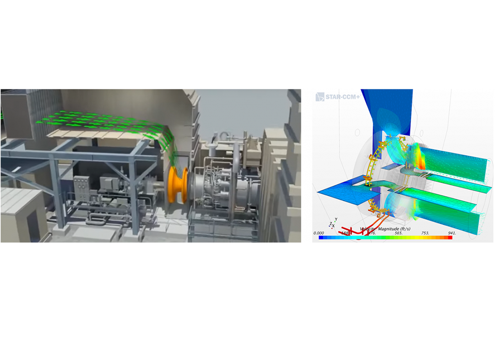
The challenge for our client (an electrical utility) is that this wet compression device is bolted onto the flow housing inlet to the gas turbine. If this device fails, then parts would directly enter the turbine, leading to an expensive repair operation plus unexpected disruption to the utility’s power grid. The graphics down below provide a generalized description of the CFD and FEA models. Air inters through the filter house and then around the housing, through some guide vanes and then into the compressor-side of the gas turbine. The CFD analysis (STAR-CCM+) provides us with component pressures over the housing and the water spray system which were then mapped onto a FEA model (FEMAP). The FEA model was then exercised through a static stress, normal modes and modal frequency analyses (NX Nastran). To verify this work, a CFD mesh convergence study was done and the FEA work was checked against hand calculations. Results assured the client that the add-on device was more than structurally adequate and could easily handle the power plant’s dominate 60 Hz vibration plus any multiples.
A case study with more information and graphics can be found under our CFD Consulting Services page.