LS-DYNA: Observations on Explicit Meshing
This is the 3rd in a series of informal articles about one engineer’s usage of LS-DYNA to solve a variety of non-crash simulation problems. The first was on LS-DYNA: Observations on Implicit Analysis, the second was on LS-DYNA: Observations on Composite Modeling and the fourth was LS-DYNA: Observations on Material Modeling.
I come from a background in implicit analysis where element quality can often be swept under the rug by the use of dense meshes and since models run quickly no one really cares about model size, i.e., ten million DOF. Whereas, what I enjoy about explicit is that it demands the upmost model preparation from the choice of element types to the creation of perfect quad and hex dominant meshes having the absolute minimum number of DOF.
What I have been noticing over the last couple of years in the explicit world is the creation of gigantic meshes that are justified by saying, “It runs just fine in four hours using 32 CPU-cores.” Although it runs, I wonder how much time was spent in debugging this beast, and also whether the mesh density was justified by experience or by the economy of using an off-shore meshing service.
What’s the Point?
I remember this saying by a famous mechanician that no model should run more than 20 minutes. In my practice, it seems that I have to make dozens of runs before I feel comfortable with the results. This 20 minute rule resonates with me and we strive to build economical models to expedite the debugging, verification and if we are lucky the validation process. Since we are all explicit experts (viz. we are using LS-DYNA), the goal of this little article is just to share some of my observations on building numerically efficient and accurate explicit models and in no way to say that we are special or have some inside lock on building the perfect explicit model. What I have learned over the years is that it is tricky building good models and if you think you have no sins, you’ll get your ass handed to you rather quickly with LS-DYNA.
Solid Element Meshing: Let’s Talk About Mesh Density and Let’s Get Over It
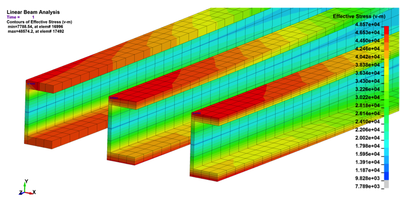
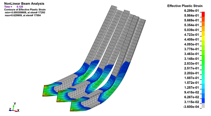
Whenever someone tells me that one needs to have at least two or four hex elements through thickness to capture bending stress – I flinch. As a generality this approach is lacking and misleading. Take a look at Figure 1. We have a stress results for a symmetric I-Beam meshed with solid elements under simple-supported bending. The flange of the I-Beam is meshed through thickness with 1, 2 and 4 hex elements. The top row of results show a linear analysis while the bottom row was run using MAT_24 with material plasticity. The figure shows that the linear and nonlinear results vary by a couple of percent. The beam’s mechanical behaviors don’t quite match one-to-one but one might say they match good enough.
Figure 1: Effects of mesh density on a deep-section I-Beam
|
Linear Analysis: Maximum von Mises stress: 47.7, 48.4 and 48.5 ksi |
|
| Non-Linear Analysis: Maximum Plastic Strain: 61.8, 63.0 and 59.7% |
|
Of course, if the load was tensile, than one element through thickness would be perfect and likewise, if it was a solid bar, then one would need two fully-integrated or four under-integrated elements to capture the mechanical response.
Before one tosses this example under the bus as unique and not applicable to your model, let’s just say that it is all an idealization and that all models are lacking in one manner or another. I strive for mesh economy and only after the model is running and all the other problems have been debugged, only then will I go back and play with mesh density. My perception is that many people over mesh since it is the low hanging fruit of model building or at times, it is out of their control.
Plate Meshing: A World of Recommendations
A good reference on how to estimate your meshing error is that provided by Schwer in his paper: “Is Your Mesh Refined Enough?” As one might suspect, the technique referenced in this paper requires the analyst to refine their meshes to assess the discretization error. This is often the rub since by the time one has the model up and running, you are loath to touch it and also, perhaps you have run out of time and budget to do any more work. Please don’t get me wrong, but I’m all on-board with doing a mesh convergence assessment and Schwer hits it dead-on in the conclusion section of his paper about the importance of engineering judgement.
For plate meshes, I’m keen on high quality and regularity. I try to shape the elements toward known high-stress locations and always try to remember what a seasoned engineer from Boeing taught me about load line mechanics: “always draw a straight line between the applied load and its constraint, whenever the structure deviates from this straight line, you’ll find a hot spot.” So I try to grade the mesh where it is going to do the most good. And what discussion of mesh quality would be complete without saying that one quality quad plate element is better than four bad ones.
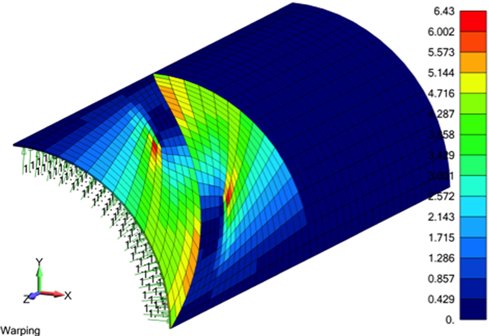
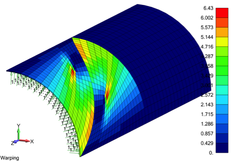
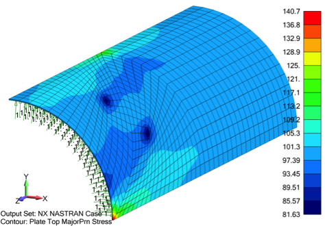
I don’t want to harp on it, since we have all heard the horror stories about poor quality meshes, but Figure 2 provides a nice illustration about the saying “if it looks good, it is good”. On the left-hand side the mesh is distorted (i.e., warped) while on the right-hand side, the mesh is regular. Since it is an example to scare newbies, the skewed mesh gives stress values that are -20 to +40% over the clean mesh where the stress value is 100. The whole point is that a trained simulation engineer understands element formulations and the underlying mechanics, they just know that one should always aim for a clean pattern (if it looks good….) and that stress results are never accepted blindly. Or as my friend Mark Sherman says, “Whenever you see a stress contour plot, just assume it is wrong.”
Figure 2: The specter of high skewed results due to poor element quality (i.e., warping) is often used to scare newbies to FEA
|
|
Then What Is The Secret To Meshing for Explicit Success?
There’s this saying that is attributed to Sir William Bragg (Nobel Prize in Physics 1915) “Never confuse hard work with hard thinking.” It has been my observation that many analysts obsess on the mesh since it provides many hours of hard work while ignoring the many other elephants in the room (hard thinking) that contribute to far more inaccuracies to the model. In a lot of cases, we have a poor understanding of the loads and even worse understanding of the material behavior that goes into our models. It is a balancing act to say the least. At the end of the day, there are no short cuts or easy one-stop-shopping metrics to create an accurate explicit mesh. What I can advocate is to focus on clean mesh patterns using high-quality elements and most likely you’ll be within 10% of reality.
Last Blurb
During dinner at a LS-DYNA conference, I was talking about the complexities of building a good mesh and this person sitting at our table remarked “you build your own meshes – what a waste of time!” It did make me feel rather out-of-date but so it goes. As the preface of this article says – we don’t do crash and hence we don’t have to build endless “bodies in white” and I understood where this person was coming from, i.e., doing repetitive meshing work. However, we are generalists and see different types of structures every month. From my experience, there is just no better way to get familiar with a structure than having to mesh it. And since explicit analysis extracts such a high-penalty for sloppy meshing, whether of poor quality or having too much of a good thing, I think we’ll stay old-fashioned for now.
Some Reference Materials
Leonard E. Schwer, Is Your Mesh Refined Enough? Estimating Discretization Error using GCI, LS-DYNA Anwenderforum, Bamberg 2008.
Laird and Waterman, See Analysis Data’s True Colors, Desktop Engineering, March 2011.